
| Particulate matter consists
of mobile, randomly-sourced, extraneous substances, other than gas bubbles,
that cannot be quantitated by chemical analysis due to the small amount
of material that it represents and to its heterogeneous composition. Injectable
solutions, including solutions constituted from sterile solids intended
for parenteral use, should be essentially free from particles that can
be observed on visual inspection. The tests described herein are physical
tests performed for the purpose of enumerating subvisible extraneous particles
within specific size ranges.
Microscopic and light obscuration procedures for the determination of particulate matter are given herein. Unless otherwise specified in the individual monograph, the article is expected to conform to the limits for the Light Obscuration Particle Count Test. All large-volume injections for single-dose infusion and those small-volume injections for which the monographs specify such requirements are subject to the particulate matter limits set forth for the test being applied, unless otherwise specified in the individual monograph. Not all injection formulations can be examined for particles by one or both of these tests. Any product that is not a pure solution having a clarity and a viscosity approximating those of water may provide erroneous data when analyzed by the light obscuration counting method. Such materials may be analyzed by the microscopic method. Emulsions, colloids, and liposomal preparations are examples. Refer to the specific monographs when a question of test applicability occurs. Higher limits are appropriate for certain articles and are specified in the individual monographs. In the tests described below for large-volume and small-volume injections, the results obtained in examining a discrete unit or group of units for particulate matter cannot be extrapolated with certainty to other units that remain untested. Thus, statistically sound sampling plans based upon known operational factors must be developed if valid inferences are to be drawn from observed data to characterize the level, of particulate matter in a large group of units. Sampling plans should be based on consideration of product volume, numbers of particles historically found to be present in comparison to limits, particle size distribution of particles present, and variability of particle counts between units. LIGHT OBSCURATION PARTICLE COUNT TEST USP Reference Standards: USP Particle Count RS. The test applies to large-volume injections labeled as containing more than 100 mL, unless otherwise specified in the individual monograph. It counts suspended particles that are solid or liquid. This test applies also to single-dose or multiple-dose small-volume injections labeled as containing 100 mL or less that are either in solution or in solution constituted from sterile solids, where a test for particulate matter is specified in the individual monograph. Injections packaged in prefilled syringes and cartridges are exempt from these requirements, as are products for which the individual monograph specifies that the label states that the product is to be used with a final filter. Test Apparatus The apparatus is an electronic, liquid-borne
particie counting system that uses a light-obscuration sensor with a suitable
sample feeding device. A variety of suitable devices of this type are commercially
available. It is the responsibility of those performing the test to ensure
that the operating parameters of the instrumentation are appropriate to
the required accuracy and precision of the test result, and that adequate
training is provided
It is important to note that for Pharmacopeial applications the ultimate goal is that the particle counter reproducibly size and count particles present in the injectable material under investigation. The instruments available range from systems where calibration and other components of standardization must be carried out by manual procedures to sophisticated systems incorporating hardware- or software-based functions for the standardization procedures. Thus, it is not possible to specify exact methods to be followed for standardization of the instrument, and it is necessary to emphasize the required end result of a standardization procedure rather than a specific method for obtaining this result. This section is intended to emphasize the criteria that must be met by a system rather than specific methods to be used in their determination. It is the responsiblity of user to apply the various methods of standardization applicable to a specific instrument. Critical operational criteria consist of the following. Sensor Concentration Limits- Use an instrument that has a concentration limit (the maximum number of particles per mL) identified by the manufacturer that is greater than the concentration of particles in the test specimen to be counted. The vendor-certified concentration limit for a sensor is specified as that count level at which coincidence counts due to simultaneous presence of two or more particies in the sensor view volume comprise less than 10% of the counts collected for 10 mm particles. Sensor Dynamic Range-The dynamic range of the instrument used (range of sizes of particles that can be accurately sized and counted) must include the smallest particle size to be enumerated in the test articles. Instrument Standardization The following discussion of instrument standardization emphasizes performance criteria rather than specific methods for calibrating or standardizing a given instrument system. This approach is particularly evident in the description of calibration, where allowance must be made for manual methods as well as those based on firmware, software, or the use of electronic testing instruments. Appropriate user validation of software and firmware systems is essential to performance of the test according to requirements. Since different brands of instruments may be used in the test, the user is responsible for ensuring that the counter used is operated according to the manufacturer's specific instructions; the principles to be followed to ensure that instruments operate within acceptable ranges are defined below. The following information for instrument standardization helps ensure that the sample volume accuracy, sample flow rate, particle size response curve, sensor resolution, and count accuracy are appropriate to performance of the test. Conduct these procedures at intervals of not more than six months. SAMPLE VOLUME ACCURACY Since the particle count from a sample
aliquot varies directly with the volume of fluid sampled, it is important
that the sampling accuracy is known to be within a certain range. For a
sample volume determination, determine the dead (tare) volume in the sample
feeder with Water for Injection or distilled water that has been passed
through a filter having a porosity of 1.2 mm
or finer. Transfer a volume of Water for Injection that is greater than
the sample volume to a container, and weigh. Withdraw through the sample
feeding device a volume that is appropriate for the specific sampler, and
again weigh the container. Determine the sample volume by subtracting the
tare volume from the combined sample plus tare volumes. Verify that the
value obtained is within ± 5% of the appropriate sample volume for
the test. Alternatively,
the sample volume may be determined using a suitable Class A graduated
cylinder (see Volumetric apparatus) .
SAMPLE FLOW RATE Verify that the flow rate is within
the manufacture's specifications for the sensor used. This may be accomplished
by using a calibrated stop watch to measure the time required for
the instrument to withdraw and count a specific sample volume (i.e the
time between beginning and ending of the count cycle as denoted by instrument
indicator lights or other
CALIBRATION Use one of the following methods: Manual Method- Calibrate the
instrument with a minimum of three calibrators, each consisting of near-monosize
polystyrene spheres drawing diameters of about 10, 15, and 25 mm,
in an aqueous vehicle. The calibrator spheres must have a mean diameter
of within 5% of the 10-, 15-, and 25-mm
nominal diameters and be standardized against materials traceable to NIST
standard reference materials. The number of spheres counted must be within
the sensor's concentration limit. Prepare suspension of the calibrator
spheres in water at a concentration of 1000 to 5000 particles per mL, determine
the channel setting that corresponds to the highest count setting for the
spheres distribution. This is determined by using the highest count threshold
setting to split the distribution into two bins containing equal number
of counts, with the instrument set in the differential count mode (moving
window half-count method). Use only the central portion of the distribution
in this calculation to avoid inclusing assymetrical portions of the peak.
The portion of the dístribution which must be divided equally, is
the count window. The window is bounded by threshold settings that will
define a threshold voltage window of ± 20% around the mean diameter
of the test spheres. The window is intended to include all single spheres
taking into account the standard deviation of the spheres and of the sensor
resolution, while excluding noise and aggregates of spheres. The value
of 20% was chosen based on the worst-case sensor resolution of 10% and
the worst-case standard deviation of
the spheres of 10%. Since the thresholds are proportional to the area of
the spheres rather than the diameter, the lower settings are determined
by the equations:
in which VL is the lower voltage setting and Vs is the voltage the peak center, and V = 1.44Vs in which VU is the upper voltage setting. Once the center peak thresholds are
determined, use these thresholds for the standards to create a regression
of log voltage versus log particle size, from which the instrument settings
for the 10- and 25-mm
sizes can be determined.
Electronic Method- Using a multichannel peak height analyzer, determine the center channel of the particle counter pulse for each standard suspension. This peak voltage setting becomes the threshold used for calculation of the voltage response curve for the instrument. The standard suspensions to be used for the calíbration are run in order, and median pulse voltages for each are determined. These thresholds are then used to generate the size response curve manually or via software routines. The thresholds determined from the multichannel analyzer data are then transferred to the counter to complete the calibration. If this procedure is used with a comparator-based instrument, the comparators of the counter must be adjusted accurately beforehand. SENSOR RESOLUTION The particle size resolution of the instrumental particle counter is dependent upon the sensor used and may vary with individual sensors of the same model. Determine the resolution of the particle counter for 10-mm particles using the monosized 10-mm calibrator spheres. The relative standard deviation of the size distribution of the standard particles used is not more than 5%. Acceptable methods of determining particie size resolution are (1) manual determination of the amount of peak broadening due to instrument response; (2) using an electronic method of measuring and sorting particle sensor voltage output with a multichannel analyzer; and (3) automated methods. Method- Adjust the particle counter
to operate in the cumulative mode or total count mode. Refer to the
calibration curve obtained earlier, and determine the threshold voltage
for the 10 mm monosized
spheres. Adjust 3 channels of the counter tobe used in the calibration
procedure as follows:
Draw a sample through the sensor, observing the count in Channel 2. When the particle count in that channel has reached approximately 1000, stop counting, and observe the counts in Channels 1 and 3. Check to see if the Channel 1 count and the Channel 3 count 168 ± 10% and 32 ± 10%, respectively, of the count of Channel 2. lf not, adjust Channel 1 and Channel 3 thresholds to meet these criteria. When these criteria have been satisfied, draw a sample of suspension through the counter until the counts in Channel 2 have reached approximately 10,000, or until an appropriate volume (e.g., 10 mL) of the spheres suspension has been counted. Verify that Channel 1 and Channel 3 counts are 168 ± 10% and 32 ± 3%, respectively, of the count in Channel 2. Record the particle size for the thresholds just determined for Channels 1, 2, and 3. Subtract the particle size for Channel 2 from the size for Channel 3. Subtract the particle size for Channel 1 from the size for Channel 2. The values so determined are the observed standard deviations on the positive and negative side of the mean count for the 10-mm standard. Calculate the percentage of resolution of the sensor by the formula:
in which So is the highest observed standard deviation determined for the spheres, Ss is the supplier's reported standard deviation for the spheres, and D is the diameter, in mm, of the spheres as specified by the supplier. The resolution is not more than 10%. Automated Method- Software is available for some counters that allows for the automated determination of sensor resolution. This software may be included in the instrument or used in conjunction with a microcomputer interfaced to the counter. The use of these automated methods is appropriate if the vendor supplies written certification that the software provides a resolution determination equivalent to the manual method and if the automated resolution determination is validated as necessary by the user. Electronic Method- Record the voltage output distribution of the particle sensor, using a multichannel analyzer while sampling a suspension of the l0-mm particle size standard. To determine resolution move the cursor of the multichannel analyzer up and down the electric potential scale from the median pulse voltage to identify a channel on each side of the 10-mm peak that has approximately 61% of the counts observed in the center channel.Use of the counter size response curve to convert the mV values of these two channels to particle sizes provides the particle size at within 1 standard deviation of the 10-mm standard. Use these values to calculate the resolution as described under Manual Method. PARTICLE COUNTING ACCURACY Determine the particle counting accuracy of the instrument, using Method 1 (for small-volume injections) or Method 2 (for large-volume injections). Method I:
(Ps - Pb)/V in which Ps is the average
particle count obtained from the suspension, Pb is the average
particle count obtained from the blank, and V is the average volume, in
mL, of the 4 portions tested. Repeat the calculations, using the results
obtained at 15 mm.
Method II: Procedure- Using standard calibrator spheres having a nominal diameter of 15 to 30 mm, prepare a suspension containing between 50 and 200 particles per mL. Degas the suspension by mild sonication (at 8 mW or less) for 30 seconds or by allowing to stand. Properly suspend the particles by stirring gently, and perform five counts on 5-mL volumes of the suspension, using the particle counter 10-mm size threshold. Obtain the mean cumulative particle count per mL. Pipet a volume of this suspension containing 250 to 500 particles into a filter funnel prepared as described for Filtration Apparatus under Microscopic Particle Count. After drying the membrane, count the total number of standard spheres collected on the membrane filter. This count should be within 20% of the mean instrumental count per mL for the suspension. Test Environment
Cleanse glassware, closures, and
other required equipment, preferably by immersing and scrubbing in warm,
nonionic detergent solution. Rinse in flowing tap water, and then rinse
again in flowing filtered water. Organic solvents may also be used to facilitate
cleaning.
To collect background counts, use a cleaned vessel of the type and volume representative of that to be used in the test. Place a 20-mL volume of filtered water in the vessel, and agitate the sample in the cleaned glassware by inversion or swirling. Degas by sonicating for 30 seconds or by allowing to stand. Swirl the vessel containing the water sample by hand or agitate by mechanical means to suspend particles. Withdraw and obtain the particle counts for three consecutive samples of not less than 5 mL each, disregarding the first count. If more than 10 particles of 10 mm or greater size, or more than 2 particles of 25 mm or greater size are observed in the combined 10-mL sample, the environment is not suitable for particulate analysis: the filtered water and glassware have not been properly prepared or the counter is generating spurious counts. In this case, repeat the preparatory steps until conditions of analysis are suitable for the test. Test Procedure TEST PREPARATION For containers having volumes of less than 25 mL, test a solution pool of 10 or more units. Single units of small-volume injections may be tested individually if the individual unit volume is 25 mL or greater. Prepare the test specimens in the following sequence. Remove outer closures, sealing bands, and any loose or shedding paper labels. Rinse the exterior of containers with filtered distilled water as described under Test Environment, and dry, taking care to protect the containers from environmental contamination. Withdraw the contents of the containers in the normal or customary manner of use, or as instructed in the package labeling, except that containers with removable stoppers may be sampled directly by removing the closure, or if test specimens are being pooled, by removing the closure and emptying the contents into a clean container. DETERMINATION Liquid Fill (where the contents
of each unit are less than 25 mL): Mix each unit by inverting it 20 times
to resuspend an particles.
Liquid Fill (where the contents of each unit are 25 mL or more, and where the option of testing individual units is selected): Mix 1 unit by inverting it 20 times. Degas the solution by sonicating or by allowing it to stand until the solution is free from air bubbles. Remove the closure, and insert the counter probe into the center of the solution. Gently agitate the contents of the unit by hand-swirling or by mechanical means. Withdraw not less than 3 aliquot portions, each not less than 5 mL in volume, into the light obscuration counter sensor. Obtain the particle counts, and discard the data from the first portion. Dry or Lyophilized Fill: Open the container, taking care not to contaminate the opening or cover. Constitute with a suitable volume of filtered water, or with the appropriate filtered diluent if water is not suitable. Replace the closure, and manually agitate the container to dissolve the drug. Allow to stand until the drug is completely dissolved. Prior to analysis, gently stir the contents of the containers by hand-swirling or by mechanical means, taking care not to introduce air bubbles or contamination. Pool or test individually the appropriate number of units, and withdraw not less than 3 aliquot portions, each not less than 5 mL in volume into the light obscuration counter sensor. Obtain the particle counts, and discard the data from the first aliquot. Solid Drugs Packaged with Diluents: For products packaged in containers that are constructed to hold the drug products and a solvent in separate compartments, mix each unit as directed in the labeling, activating and agitating each unit so as to ensure thorough mixing of the separate components. Analyze the solutions as described under Liquid Fill. Multiple-dose Containers: For products labeled Pharmacy Bulk Packages, proceed for each unit as directed under Test Preparation, calculating the results on the basis of a sample volume that is equal to the maximum dose stated in the labelling. For the calculations below, consider a maximum-dose volume to be the equivalent of the contents of one full container. Calculations: Pooled Samples (Small-volume Injections)- Average the counts from the 2 or more aliquot portions analyzed. Calculate the number of particles in each container by the formula: PVt/Van in which P is the average particle count obtained from the portion analyzed, Vt is the volume of pooled sample, in mL, Va is the volume, in mL, of each portion analyzed, and n is the number containers pooled. Individual Samples (Small-volume Injections)- Average the counts obtained for the 5-mL or greater aliquot portions from each separate unit analyzed, and calculate the number of particles in each container by the formula: PV/Va, in which P is the average particle count obtained from the portions analyzed, V is the volume, in mL, of the tested unit, and Va is the volume, in mL, of each portion analyzed. Individual Unit Samples (Large-volume Injections)- Average the counts obtained for the two or more 5-mL aliquot portions taken from the solution unit. Calculate the number of particles in each mL taken by the formula: P/V, in which P is the average particle count for an individual 5 mL or greater sample volume, and V is the volume, in mL, of the portion taken. Interpretation: The injection meets the requirements of the test if the average numbers of particles present in the units tested do not exceed the appropriate value listed in Table 1. lf the average number of particles exceeds the limit, test the article by the Microscopic Particle Count Test. Table 1. Light Obscuration Test Particle
Count.
MICROSCOPIC PARTICLE COUNT TEST The microscopic particulate matter test may be applied to both large-volume and small-volume injections. This test enumerates subvisible, essentially solid, particulate matter in these products on a per-volume or per-container basis, after collection on a microporous membrane filter. Some articles cannot be tested meaningfully by light obscuration. In such cases, individual monographs specify only this microscopic assay. Solutions exempted from analysis using the microscopic assay are identified on a monograph basis. Examples are solutions of viscosity too high to filter readily (e.g., concentrated dextrose, starch solutions, or dextrans). Similarly, products known to contain amorphous semiliquid or otherwise morphologically indistinct materials should be tested by the microscopic method. These materials show little or no surface relief and present a gelatinous or film-like appearance. Since in solution this material consists of units on the order of 1 mm or less, which may be counted only after aggregation or deformation on an analytical membrane, interpretation of enumeration may be aided by testing a sample of the solution by the light obscuration particle count method. Test Apparatus Microscope- Use a compound binocular microscope that corrects changes in interpupillary distance by maintaining a constant tube length. The objective and eyepiece combination of lenses must give a magnification of 100 ± 10 X. The objective must be of 10X nominal magnification, a planar achromat or better in quality, with a minimum numerical aperture of 0.25. In addition the objective must be compatible with an episcopic illuminator attachment. The eyepieces must be of 10X magnification, with a field number of >l5 (widefield). In addition, eyepiece must be designed to accept and focus an eyepiece graticule. The microscope must have a mechanical stage capable of holding and traversing the entire filtration area of a 25-mm or 47 mm membrane filter. Illuminators- Two illuminators are required. One is an external, focusable auxiliary illuminator adjustable to give incident oblique illumination at an angle of lOº to 20º. The other is an episcopic brightfield illuminator internal to the microscope. Both illuminators must be of a wattage sufficient to provide a bright, even source of illumination and may be equipped with blue day-filters to decrease operator fatigue during use. Diameter Graticule-Use a circular diameter graticule (see Figure 1) matched to the microscope model objective and eyepiece such that the sizing circles are within 2% of the stated size at the plane of the stage. 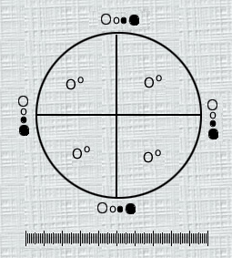 Fig. 1.- Circular diameter graticule. The large circle divided by crosshairs into quadrants is designated the graticule field of view (GFOV). Transparent and black circles having 10-um 25-mm diameters at 100X are, provided as comparison scales for particle sizing. Micrometer-Use a stage micrometer, graduated in 10-mm increments, that is certified by NIST. Filtration Apparatus- Use a filter funnel suitable for the volume to be tested, having a minimum diameter of about 21 mm. The funnel is made of plastic, glass, or stainless steel. Use a filter support made of stainless steel screen or sintered glass as the filtration diffuser. The filtration apparatus is equipped with a vacuum source, a solvent dispenser capable of delivering solvents filtered at 1.2 mm or finer retention rating at a range of pressures 10 psi to 80 psi, and membrane filters (25 mm or 47 mm nongridded or gridded, black or dark gray, of mixed cellulose ester with a porosity of 1.0 mm or finer). Use blunt forceps to handle membrane filters. Test Environment A laminar flow hood or other laminar
airflow enclosure, having a capacity sufficient to envelope the area in
which the analysis is prepared, with HEPA-filtered air having not more
than 100 particles (0.5 mm
or smaller) per cubic foot. For the blank determination, deliver from the
pressure dispenser a volume of filtered water equal to the sample volume
into the Etration Apparatus. Apply vacuum and draw the entire volume of
water through the membrane filter.
Preparation of Test Apparatus Throughout this procedure, preferably
use suitable powder-free gloves, and thoroughly clean glassware and equipment
that have been rinsed successively with a warm, residue-free solution of
detergent, hot water, filtered distilled or deionized water, and isopropyl
alcohol.
The number of samples chosen must be adequate to provide a statistically sound assessment of whether a batch or other large group of units represented by the samples meets or exceeds the limit. Test a solution pool of 10 or more units, or test individual units. For large-volume injections, individual units are tested. MICROSCOPE PREPARATION Place the auxiliary illuminator close to the microscope stage, focusing the illuminator to give a concentrated area of illumination on a filter membrane positioned on the microscope stage. Adjust the illuminator height so that the angle of incidence of the light is 10º to 20º with the horizontal. Using the internal episcopic brightfield illuminator, fully open the field and aperture diaphragms. Center the lamp filament, and focus the microscope on a filter containing particles. Adjust the intensity of reflected illumination until particles are clearly visible and show pronounced shadows. Adjust the intensity of episcopic illumination to the lowest setting, then increase the intensity of episcopic illumination until shadows cast by particies show the least perceptible decrease in contrast. OPERATION OF CIRCULAR DIAMETER GRATICULE The relative error of the graticule used must initially be measured with an NIST-certified stage mierometer. To accomplish this, align the graticule micrometer scale with the stage mierometer so that they are parallel. (Compare the scales, using as large a number of graduations on each as possible). Read the number of graticule scale divisions, GSD, compared to stage micrometer divisions, SMD. Calculate the relative error by the formula: (GSD - SMD) 100 SMD. A relative error of ± 2% is
acceptable. The basic technique of measurement applied with the use of
the circular diameter graticule is to transform mentally the image of each
particle into a circle and then compare it to the 10- and 25 mm
graticule reference circles. The sizing process is carried out without
superimposing the particle on the reference circles; particles are not
moved from their locations within the graticule field of view (the large
circle) for
Rotate the graticule in the right microscope eyepiece so that the linear scale is located at the bottom of the field of view, bringing the graticule into sharp focus by adjusting the right eyepiece diopter ring while viewing an out-of-focus specimen. Focus the microscope on a specimen, looking through the right eyepiece only. Then, looking through the left eyepiece, adjust the left eyepiece diopter to bring the specimen into sharp focus. PREPARATION OF FILTRATION APPARATUS Preferably, wash the filtration funnel, base, and diffuser in a solution of liquid detergent and hot water. Rinse with hot water. Following the hot water rinse, apply a second rinse with filtered Purified Water, using a pressurized jet of water over the entire exterior and interior surfaces of the filtration apparatus. Repeat the pressurized rinse procedure using filtered isopropyl alcohol. Finally, using the pressurized rinser, rinse the apparatus with filtered Purified Water. Assemble the cleaned filtration apparatus
with the diffuser on top of the filtration base, placing the clean membrane
filter on top of the diffuser. Remove a membrane filter from its container
using ultracleaned blunt forceps. Use a low pressurized stream of filtered
Purified Water to wash both sides of the filter thoroughly by starting
at the top and sweeping back and forth to the bottom. Place the funnel
assembly on top of the filtration base, and
TEST PREPARATIONS Liquid Fill (Large or Small-Volume Injections): Thoroughly mix the units to he tested by inverting 20 times. Clean the outer surface of the solution container thoroughly with pressurized filtered Purified Water. Open the units in a manner consistent with generation of lowest possible numbers of background particles. In a cleaned container, open and combine the contents of not less than 10 containers, or filter the contents of individual containers. Dry Powder Vials: Constitute the material with an appropriate diluent using the method least likely to introduce extraneous contamination. Add the constituted solütion to the filter funnel atop a sufficient volume of filtered water to bring the total volume to be filtered to about 100 mL, or use a smaller funnel. Pool the desired number of units, and proceed as directed under Test Procedure. Drug-Diluent Products: For products packaged in containers that are constructed to hold the drug product and a solvent in separate compartments, mix each unit as directed in the labeling, activating and agitating each unit in order to ensure thorough mixing of the separate components. Proceed as directed under Test Procedure.
[NOTE-If a small-volume injection unit of 25 mL or a solution pool of less than 25 mL total volume is to be tested and the partial count procedure is to be used, a volume of diluent sufficient to bring the total volume to about 100 mL may be added or, alternatively, a smaller funnel may be used. After adding the pooled material, apply vacuum and proceed with fíltration as specified above for a liquid solution unit. Enumeration of Particles:
The microscopic test described in this section is flexible in that
it can count, in particles per mL, specimens containing 1 particle per
mL as well as those containing significantly higher numbers of particles
per mL.
TOTAL COUNT PROCEDURE In performance of a total count, the graticule field of view (GFOV) defined by the large circle of the graticule is ignored and the vertical crosshair is used. Scan the entire membrane from right to left in a path that adjoins but does not overlap the first scan path. Repeat this procedure, moving from left to right to left until all particles on the embrane are counted. Record the total number of particles that are 10 um or larger and the number that are 25 mm or larger. For large-volume injections calculate the particle count, in particles per mL, for the unit tested by the formula: P/V, where P is the total number of particles counted, and V is the volume, in mL, of the solution. For small-volume injections calculate the particle count, in particles per container, by the formula: P/N in which P is the total number of particles counted, and N is the number of units pooled (1 in the case of a single unit) PARTIAL COUNT PROCEDURE If a partial count of particles on a membrane is to be performed the analyst must first ensure that an even distribution of particles is present on the membrane. This is assessed by rapid scanning in order to look for clumps of particles. None should be present. Count the 10-mm or larger particles in one GFOV at the edge of the filtration area as well as those in the center of the GFOV. The number of >10-mm or larger particles in the GFOV with the highest total particle count is not more than twice that of the GFOV with the lowest particle count. Reject a filter failing these criteria, and prepare another if a partial count procedure is used or, alternatively, analyze this membrane by the total count method. The normal number of GFOV counted
for a partial count is 20. If a smaller confidence interval about the result
is desired, a larger number of fields and particles may be counted. Count
all particles that have a circular area diameter of 10 mm
or larger and 25 mm
or larger within the GFOV and those that are in contact with the right
side of the GFOV circle. Do not count particles outside of the GFOV. Ignore
those that touch the left side of the GFOV circle. The dividing line between
right and left sides of the GFOV circle is the vertical cross hair. [NOTE-
Make the best possible judgment on particle size without changing the microscope
magnification or illumination].
in which P is the number of particles counted. In the event that filtration of a solution results in a particle count too high to enumerate accurately in a GFOV, a single quadrant of the GFOV may be counted with a 47-mm filter and a fractional aliquot of the unit. To perform a partial count of the
particles on a membrane, start at the right center edge of the filtration
area and begin counting adjacent GFOVs. When the left edge of the filtration
area is reached move one GFOV toward the top of the filter and continue
counting GFOVs by moving in the opposite direction.
For large-volume injections, if a partial count procedure for the >10 mm and >25mm size ranges is used, calculate the particles per mL, by the formula: PAt/ApV, in which P is the number of particles counted, At is the filtration area in mm2 of the membrane, Ap is the partial area counted in mm2 based on the number of graticule fields counted, and V is volume,in mL, of solution filtered. For a solution pool (for small-volume injection units containing less than 25 mL) or for a single unit of a small-volume injection, calculate the number of particles per unit by the formula: pAt/Apn in which n is the number of units counted (1 in the case of a single unit), and the other terms are as defined above. Interpretation The injection meets the requirements of the test if the average number of particles present in the units tested does not exceed the values listed in Table 2. Table 2. Microscopic Method Particle
Count.
|